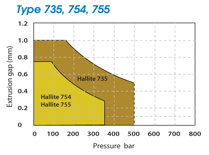
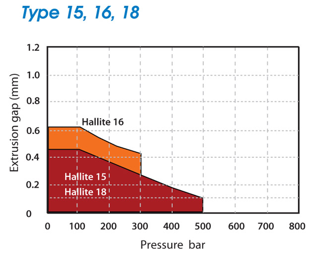
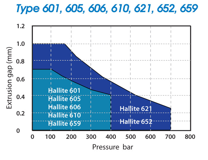
Hallite Seals’ product data sheets give information indicating the allowable extrusion gap a seal can see at pressure during its working life. The extrusion gap can be calculated using the tolerance build ups within the cylinder and any dilation that may occur under pressure.
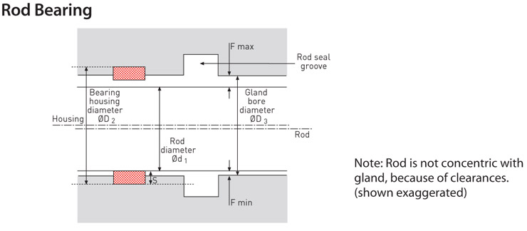
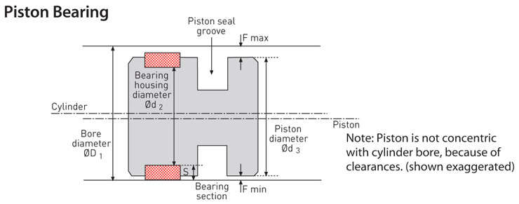
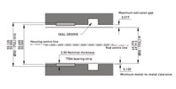
Maximum extrusion gap = F max (see drawing below).
F max is the maximum extrusion gap for the seal
Minimum metal to metal clearance = F min (see drawing below).
F min for cylinders with minimal side loading should be >0.1mm (0.004″).
Rods
Maximum extrusion gap: F max = ((ØD3 max + ØD2 max) /2) – S min – Ød1 min
Minimum metal to metal clearance (extrusion gap): F min = S min – ((ØD2 max – ØD3 min) /2)
Pistons
Maximum extrusion gap: F max = ØD1 max – S min – ((Ød3 min + Ød2 min) /2) + dilation
Minimum metal to metal clearance (exclusion gap): F min = S min – ((Ød3 max – Ød2 min) /2)
Calculate both F max and F min.
Ensure the F min is greater than 0.1mm (0.004″) and F max is less than the maximum extrusion gap stated on the seal data sheet at the application’s working pressure. For built-in metal bearings, the extrusion gap calculation is simpler.
For F max:
Rod = ØD3 max – Ød1 min
Piston = ØD1 max – Ød3 min + dilation
F min must be zero
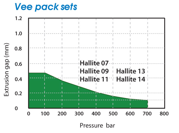
Extrusion is closely linked to pressure and temperature. In general, the best seal performance and life is provided by specifying the smallest possible extrusion gap.
The figures shown for the extrusion gap within the operating conditions of Hallite’s product data sheets, relate to the maximum permissible, worst case situation with the gap all on one side.
-
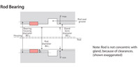 Rod BearingNote: Rod is not concentric with gland, because of clearances. (shown exaggerated)
 -
 Piston BearingNote: Piston is not concentric with cylinder bore, because of clearances. (shown exaggerated)
 -
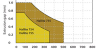 735, 754, 755
Extrusion gaps and metal-to-metal clearance
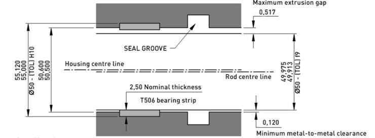
The use of remote bearing strips, such as Hallite 506, often creates a conflict between maximising the metal-to-metal clearance, to avoid metal-to-metal contact, and minimising the extrusion gap of the seal. The design decisions that have to be made in this respect are not trivial. The following examples show the effects of looser and tighter tolerances on the minimum metal-to-metal clearance and the maximum extrusion gap. The values have been calculated using the housing design formulae. No allowance has been made for the deflection of the bearings under side load, and, in the case of the piston examples, for the cylinder dilation.
-
 T506Gland for 50mm rod using ‘standard’ tolerances
 -
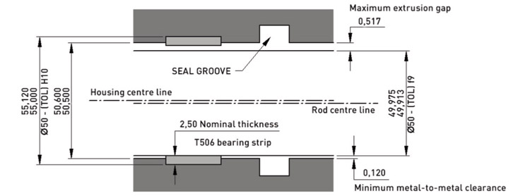
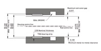 T506Gland for 50mm rod with tighter tolerances, showing that the minimum metal-to-metal clearances can be increased and the maximum extrusion gap reduced
 -
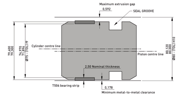
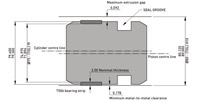 T506Piston for 80mm bore using ‘standard’ tolerances

Once the maximum extrusion gap has been calculated the correct seal can be specified with regard to the required operating pressure of the cylinder. For further advice, please contact Hallite Seals.


