The dynamic surface finish has an immense influence on operation and service life of a sealing component
Surface roughness
If the surface is too smooth, it will not properly retain lubrication and will cause excessive seal wear due to frictional heat. If the surface is too coarse, premature seal failure may occur due to the roughness of the surface, hence causing small cuts or scores in the sealing lip. Proper surface finish is critical in assuring maximum seal performance and life within a given application.
The static sealing and housing surface also has a significant influence on the operation and service life of a seal. Though the surface finish requirements are not as severe, it is critical to ensure surface finish recommendations are met to maximise seal performance and life.
Dynamic surface finishes
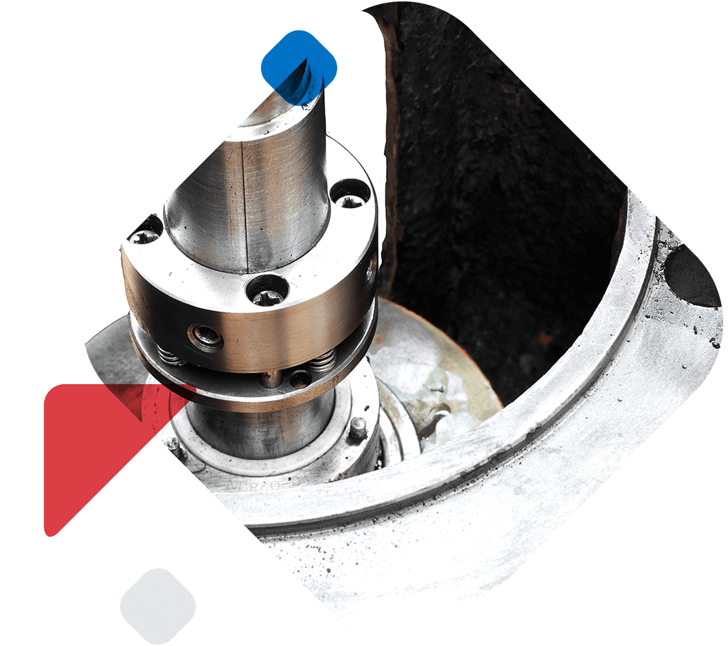
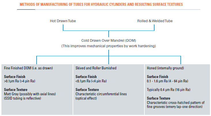
Piston rods are generally hard chrome plated. The hardness target should be at least 67 Rockwell C (900 HV/10). This gives an excellent tribological surface, and provided the rods are produced by an established supplier within a surface finish range of 0.1 to 0.3 μm Ra (4-12 μin Ra), no major problem should ensue. The optimum surface finish may also depend on the seal material. Bore surface finishes can be more problematic. The typical methods of achieving bore finishes are summarized in the figure below and bulleted details:
Drawn Over Mandrel (DOM) tubing as produced, can be either adequate or inadequate depending on the actual surface texture achieved and the application.
Special Smooth Inside Diameter (SSID) DOM: With the advent of improved manufacturing processes, SSID tubing is more commonplace than it was years ago. In certain circumstances however, SSID finishes, just like its rougher finish relative DOM tube, can lead to premature wear of the seal through flow erosion. Careful specification and regular quality inspections are recommended if SSID tube is to be used.
Optimally, skived & roller burnished or honed tube is preferred.
Skived & roller burnished tubing is very smooth (less than 0.1μm Ra) (4 μin Ra). Rubber sealing elements are more susceptible to damage due to the smoother surfaces.
Honed tube (produced between 0.1 and 0.4 μm Ra) (4-16 μin Ra) is potentially the most expensive, but has the best finish and is known to be the friendliest to mating sealing elements.
Static surface finishes
The static sealing surface finish must not be ignored in the control of leakage. Generally, these are fine turned and should be free from chatter marks.
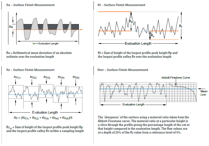
Critical surface finish measurements for sealing
Many parameters can be used to define surface finishes, which are explained in ISO 4287 and ISO 4288. The most commonly used in the fluid power industry include:
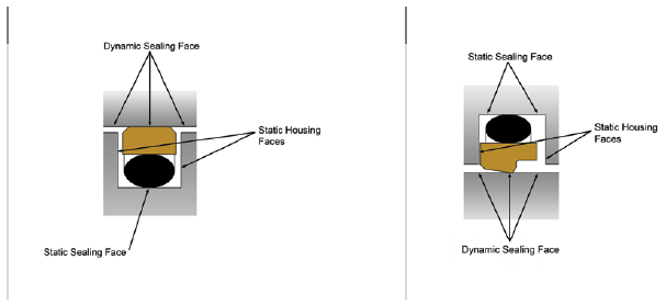
Sealing face profiles
Surface finish recommendations – PTFE materials
Metric
Inch
Rmr*
Surface Roughness
µmRa
µmRz
µmRt
µinRa
µinRz
µinRt
Dynamic Sealing Ød1
0.05 – 0.2
1.6 max
2 max
2 – 8
63 max
157 max
50-80%
Static Sealing Face ØD1
1.6 max
6.3 max
10 max
63 max
250 max
394 max
Static Housing Faces L1
3.2 max
10 max
16 max
125 max
394 max
630 max
Rmr is measure at a depth of 25% of the Rz value based upon a ference level (zero line) at 5% material/bearing area.
Rmr is measure at a depth of 25% of the Rz value based upon a ference level (zero line) at 5% material/bearing area.
Use & fitting of seals
1. Specify piston and gland bearings which are adequately proportioned to support the cylinder loads.As a result of mounting misalignments and / or the working action of the cylinder, piston and gland bearings will be subjected to side-loading, causing damage to the rod or the tube surface and hence the seal, if the bearings are inadequate.
2. Ensure that seals are stored distortion free in a cool, dry and dark place prior to fitting.
3. Check that the seal housing is free from damage likely to harm the seal. Remove all sharp edges and burrs from metal parts, paying particular attention to ports, grooves and threads over or through which the seal passes during assembly.
4. Clean all seal housing areas, ensuring that all metallic particles and other contaminants have been removed. Check that other surfaces adjacent to the passage of the seal on fitting are also free of dirt, swarf or other contaminants. Check that both static and dynamic housing surface finishes meet specifications.
5. Where the difference between a thread diameter over which the seal must pass and the seal diameter is small, use some form of protection over the thread, such as a fitting sleeve made of hard plastic.
6. Check that the seal is of the correct type, part number and size, and that the specified material is correct. If there is any doubt regarding the material contact your local Hallite sales office.
7. Lubricate all seals and metal components liberally with clean operating fluid or a compatible grease prior to assembly. N.B. Silicone grease should not be used in normal hydraulic applications.
8. Where seals fitted to sub-assemblies, such as pistons, are awaiting further fitting operations, ensure that the seals are not subjected to any misaligned or localised loading which will cause local deformation. Ensure that sub-assemblies remain clean.
9. The use of metal levers is not recommended but should they be used it is imperative that they are completely smooth and free from nicks and burrs. When using them ensure that the metal surfaces adjacent to the seal are not damaged.
10. Flush the hydraulic system thoroughly before connecting the cylinder to it.
Housing designs
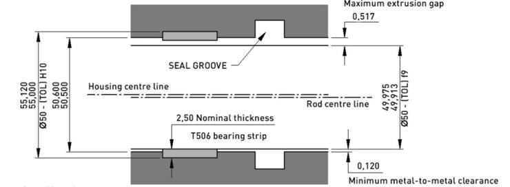
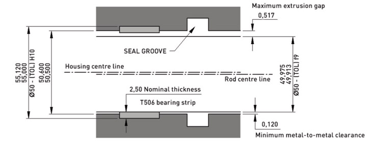
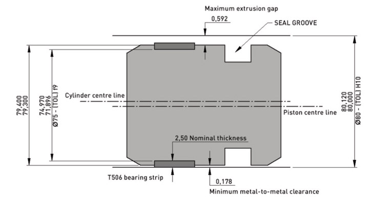
Maximum extrusion gap = F max (see drawing below). F max is the maximum extrusion gap for the seal
Minimum metal to metal clearance = F min (see drawing below). F min for cylinders with minimal side loading should be >0.1mm (0.004″).
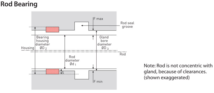
Rods Maximum extrusion gap: F max = ((ØD3 max + ØD2 max) /2) – S min – Ød1 min Minimum metal to metal clearance (extrusion gap): F min = S min – ((ØD2 max – ØD3 min) /2)
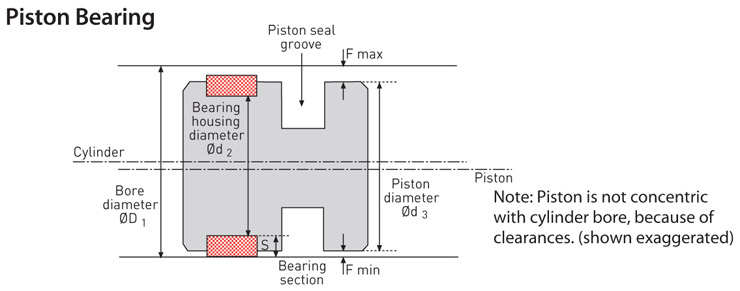
Pistons Maximum extrusion gap: F max = ØD1 max – S min – ((Ød3 min + Ød2 min) /2) + dilation Minimum metal to metal clearance (exclusion gap): F min = S min – ((Ød3 max – Ød2 min) /2)
Calculate both F max and F min.
Ensure the F min is greater than 0.1mm (0.004″) and F max is less than the maximum extrusion gap stated on the seal data sheet at the application’s working pressure. For built-in metal bearings, the extrusion gap calculation is simpler.
For F max: Rod = ØD3 max – Ød1 min Piston = ØD1 max – Ød3 min + dilation F min must be zero
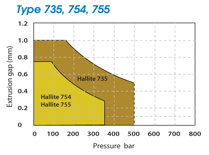
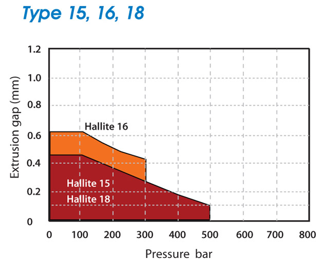
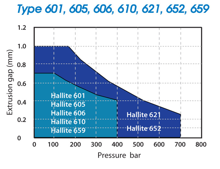
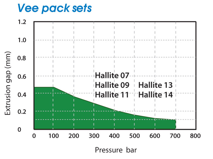
Extrusion is closely linked to pressure and temperature. In general, the best seal performance and life is provided by specifying the smallest possible extrusion gap.
The figures shown for the extrusion gap within the operating conditions of Hallite’s product data sheets, relate to the maximum permissible, worst case situation with the gap all on one side.
Rod bearing. Note: Rod is not concentric with gland, because of clearances. (shown exaggerated)
The use of remote bearing strips, such as Hallite 506, often creates a conflict between maximising the metal-to-metal clearance, to avoid metal-to-metal contact, and minimising the extrusion gap of the seal. The design decisions that have to be made in this respect are not trivial. The following examples show the effects of looser and tighter tolerances on the minimum metal-to-metal clearance and the maximum extrusion gap. The values have been calculated using the housing design formulae. No allowance has been made for the deflection of the bearings under side load, and, in the case of the piston examples, for the cylinder dilation.
Once the maximum extrusion gap has been calculated the correct seal can be specified with regard to the required operating pressure of the cylinder. For further advice, please contact Hallite Seals.
Storage of seals
The following recommendations indicate the most suitable conditions for storing elastomeric items, whether as a single item or composite product.
1. Temperature
Storage temperatures should not exceed 50°C. Low temperatures are not permanently harmful provided the rubber items are handled carefully and not distorted. When taken from low temperatures items should be raised to approximately 30°C before they are used.
2. Humidity
Optimum humidity is about 65% in a draft-free atmosphere.
3. Light
Protection from direct sunlight and strong artificial light with a high ultraviolet content is important. Unless packed in opaque containers, it is advisable to cover windows with red or orange screens or coatings.
4. Oxygen and ozone
Elastomeric items should be protected from circulating air wherever possible. As ozone is particularly harmful to rubber, storage rooms should be free from equipment that may give rise to electric sparks or discharge. Wrapping, storage in airtight containers or other suitable means should be used for vulcanised rubber items.
5. Deformation
Where possible, rubber items should be stored in a relaxed position, free from tension or compression. Laying the item flat and avoiding suspension or crushing keeps it free from strain and minimises deformation.
6. Contact with liquid and semi-solid material
Contact with liquids and semi-solid materials, particularly solvents, such as oils or greases should be avoided unless so packed by the manufacturer.
7. Contact with metals
Metals such as manganese, iron and copper, or copper alloys can have a harmful effect on rubber. A layer of paper, polyethylene or cellophane will keep these separated.
8. Contact with non-metals
Contact with other rubbers or creosotes should be avoided.
9. Stock rotation
Elastomers should be stored for as short a period as possible, and strict stock rotation should be practised.
10. Cleaning
Organic solvents such as trichloroethylene, carbon tetrachloride and petroleum are the most harmful agents. Soap and water and methylated spirits are the least harmful, and all parts should be dried at room temperature before use.
11. Shelf life
The table shows the storage life of seal components made from the more common materials under ideal conditions. Storing under less than ideal conditions will reduce the life.
Careful inspection of the following should be made before installation after storage:
a. Mechanical damage b. Permanent distortion c. Cracks or surface crazing d. Tackiness or surface softening/hardening
Thin components (less than 1.6mm {1/16in}) tend to be more critically affected.
The appearance of ‘bloom’ is relatively unimportant, except in certain non-toxic applications.
Housing & installation data
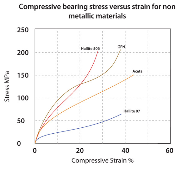
Hallite 87, 506 & 533 bearing strip
Hallite 87 strip is a low friction bronze filled PTFE compound produced in a flat tape style ready for easy cutting to size to suit individual applications and is particularly effective in friction conscious applications such as servo cylinders.
Hallite 506 can be supplied in spiral lengths, generally in 10 metre, as individual cut bearings and also in 10 metre lengths packed flat in a box dispenser. Hallite 506 bearing strip is manufactured to extremely accurate thickness tolerances, ensuring reliable cylinder alignment. Other sizes of type 506 are available on request, special sections and diameters can also be produced to suit individual requirements.
Bearing type
Standard material
87
PTFE + bronze
506
Polyester + PTFE
533
GFN
Bearing strip housing tolerances
As tolerances are not specified “on line” for types 87 & 506, please refer to the information below and on the next page for tolerances as indicated on the product’s data sheet.
Heavy duty lifting equipment Agricultural equipment Light duty off-road vehicles Cranes and lifting platforms Heavy duty machine tool Injection moulding machines Some auxiliary mining machinery Aircraft equipment Presses Heavy duty tippers (telescopic) Heavy duty mechanical handling
Foundry and metal fabrication plant Mining machinery Roof supports Heavy duty earth moving machinery Heavy duty off-road vehicles Heavy duty presses
From many years of application experience with sealing hydraulic equipment, supported by the results from an extensive test programme, we know that it is necessary to link the three main operating features of speed, pressure, and temperature to achieve a satisfactory seal performance.
After carefully considering each product we are able to specify the maximum speed and pressure within a temperature range within which the seal will operate safely. If your operating conditions do not comply with those recommended please send your details to your local Hallite sales office.
Download centre
If you need information on specific products, locate the product using the product finder or browse for the product you are looking for.
Hallite webinars & podcasts
Register now! to access our latest webinars and podcasts.
Webinar 1: “Introduction to Hydraulic Seal Design, Selection, and Application” — an informative 40-minute video recording immediately available on-demand.
Webinar 2: “Demonstration of the Fluid Power 101 App and a New Digital Platform Showcasing Partnership with the Milwaukee School of Engineering” – an informative 25-minute video recording immediately available on-demand.
Webinar 3: “Beyond the Basics: Testing to Understand how Material Chemistry Drives Seal Performance” – an informative 35-minute video recording immediately available on-demand.
Podcast 1: “Choosing the Right Rod Seal for Your Hydraulic Application” – an informative 35-minute voice recording immediately available on-demand.
Podcast 2: “Continued Seal Advancements and the Extension of Life for Mobile Equipment” – an informative 32-minute voice recording immediately available on-demand.
Armorlene® PTFE product profiles We’ve expanded our portfolio again, continuing to offer our customers around the world the reliable products and services they depend upon from Hallite.
Hallite corporate capabilities An overview of manufacturing capabilities, location, testing, materials and products for common applications.
High performance sealing solutions Hallite products, engineered in a wide variety of advanced materials, are chosen by leading manufacturers for their exceptional performance in the most demanding, safety-critical high specification applications.
Sealing systems for the mining industry Working in partnership and liaising with manufacturers worldwide, Hallite fully understands the demanding applications and the severe working conditions in which mining equipment operates.
Sealing systems for off-highway equipment Hallite Seals offer both the OEM and the end user a range of products specifically designed and manufactured to service the global off-highway industry.
Hallite Fastrack Using the latest CAD/CAM our CNC machines are designed to produce rubber and plastic parts to customer’s drawings or by utilising one of the 100 plus computerised profiles.
Product brochures
Hallite’s AEON® hollow rubber springs Hallite’s extensive range of AEON® progressive rubber springs have improved suspension performance both as a sole suspension and as a spring helper for over 40 years.
Hallite 869 wiper seal The Hallite 869 double-lipped, metal-cased wiper is designed to press fit into open groove housings of popular Asian housing sizes.
Hallite 80 rotary pressure seal The Hallite 80 rotary pressure seal is a seal designed specifically for use in hydraulic swivel joints.
Hallite 83 tri-seal assembly The tri-seal consists of two split plastic anti-extrusion rings and a nitrile synthetic rubber-sealing member.
Hallite 621 rod seal The Hallite 621 rod seal is engineered specifically for demanding applications which are subject to extreme and arduous operating conditions.
Hallite 720 unitized piston Hallite’s unitised piston continues to establish and develop itself as a unique solution for our customers’ many and varied applications.
Hallite 735 compact double acting piston seal The Hallite 735 is a compact double acting piston seal designed for one piece pistons and is suitable for low to high pressure, medium to heavy duty applications.
Hallite 820 high performance rod wiper Designed with the same look and feel as Hallite’s popular T842 and engineered to fit the same ‘D’ groove as our T520 wiper, the T820 wiper was developed specifically for harsher environments where the wiper is subject to numerous contaminants. This is common in agriculture, off-highway and forestry equipment.
Hallite 844 double lip wiper The Hallite 844 wiper has been specifically developed for cylinders used in demanding off-highway applications.
Hallite 844 raschiatore Il raschiatore Hallite 844 è stato specificatamente sviluppato per cilindri che operano nel settore del movimento terra. Il suo profilo con doppio labbro si abbina con l’impiego della speciale tenuta stelo Hallite 663.
Hallite 860 metal cased wiper The Hallite 860 is a metal cased wiper designed to press-fit into open groove housings.
Hallite bearings, wear rings & bushings High performance Hallite bearing and wear ring products are offered in a wide range of materials, configurations, and styles, that meet the needs of the most demanding applications for reciprocating piston and rod bearings.
Hallite unitized piston accumulator Hallite’s unitized piston accumulator works and functions as one unit, replacing multi-part piston accumulators.
Hallite wiper brochure Hallite products, engineered in a wide variety of advanced materials, are chosen by leading manufacturers for their exceptional performance.
Hallite materials Hallite’s materials, including thermo plastic elastomers, bearing compounds, nitrile rubbers and rubber-fabric, provide the characteristics that complement and enhance seal designs, providing products for many applications.
Fluid compatibility
Use the tables below to work out which materials best suit your specific system and operating environment. If you need information on specific products, locate the product using the product finder or browse for the product you are looking for.
Maximum continous service temperature in fluids °C
NBR 70 IRH NBR 90 IRHD Nitrile (medium)
+100-30
+120-30
+100
+90
+100
+100
FKM 75 IRHD FKM 90 IRHD Fluoro-elastomer
+200-20
+250-20
+150
+150
+160
+100
EPDM 70 IRHD EPDM 80 IRHD
+120-50
+150-50
NS
NS
NS
NS
VMQ 70 IRHD Silicone
+200-55
+250-55
*
*
*
*
HNBR 75 IRHD Hydrogenated nitrile
+130-30
+150-30
+130
+110
+130
+100
IIR Butyl
+120-40
+140-40
NS
NS
NS
NS
FFKM Perfluoro-elastomer
+200 -20
+300 -40
+150
+150
+160
+100
AU Polyester PU
+100-30
+110-30
+100
+100
+100
+100
EU Polyether PU
+100-40
+110-45
+100
+100
+100
+100
Polyester-elastomer
+100-40
+120-40
+100
+100
+100
+100
PA Polyamide
+100-40
+120-40
+100
+100
+100
+100
POM Acetal
+100-45
+120-40
+100
+100
+100
+100
PPS Polyphenylene sulphide
+200-40
+200-40
+150
+150
+160
+100
PTFE Polytetra-fluoroethylene
+200-200
+200-200
+150
+150
+160
+100
Thermosetting Polyester Resin
+100-50
+130-200
+100
+100
+100
+100
PEEK Polyether-etherketone
+250-65
+300-65
+150
+150
+160
+100
Materials
Continual material service temperature range C
Intermitent material service temperature range C
Motor Oil based greases
Silicon oil greases
+100-30
+250-50
Maximum continous service temperature in fluids °C
NBR 70 IRH NBR 90 IRHD Nitrile (medium)
+100-30
+120-30
+100
+100
FKM 75 IRHD FKM 90 IRHD Fluoro-elastomer
+200-20
+250-20
+100
+200
EPDM 70 IRHD EPDM 80 IRHD
+120-50
+150-50
NS
+120
VMQ 70 IRHD Silicone
+200-55
+250-55
+100
*
HNBR 75 IRHD Hydrogenated nitrile
+130-30
+150-30
+100
+130
IIR Butyl
+120-40
+140-40
NS
+120
FFKM Perfluoro-elastomer
+200 -20
+300 -40
+100
+200
AU Polyester PU
+100-30
+110-30
+100
+100
EU Polyether PU
+100-40
+110-45
+100
+100
Polyester elastomer
+100-40
+120-40
+100
+100
PA Polyamide
+100-40
+120-40
+100
+100
POM Acetal
+100-45
+120-40
+100
+100
PPS Polyphenylene sulphide
+200-40
+200-40
+150
+200
PTFE Polytetra-fluoroethylene
+200-200
+200-200
+100
+200
Thermosetting Polyester Resin
+100-50
+130-200
+100
+100
PEEK Polyether-etherketone
+250-65
+300-65
+100
+250
Materials
Continual material service temperature range C
Intermitent material service temperature range C
Diesel Fuel
Fuel for gasoline/petrol engines - normal
Fuel for gasoline/petrol engines - super
Maximum continous service temperature in fluids °C
NBR 70 IRH NBR 90 IRHD Nitrile (medium)
+100-30
+120-30
*
*
*
FKM 75 IRHD FKM 90 IRHD Fluoro-elastomer
+200-20
+250-20
+150
+150
+150
EPDM 70 IRHD EPDM 80 IRHD
+120-50
+150-50
NS
NS
NS
VMQ 70 IRHD Silicone
+200-55
+250-55
NS
NS
NS
HNBR 75 IRHD Hydrogenated nitrile
+130-30
+150-30
*
*
*
IIR Butyl
+120-40
+140-40
NS
NS
NS
FFKM Perfluoro-elastomer
+200 -20
+300 -40
+150
+150
+150
AU Polyester PU
+100-30
+110-30
+60
+60
+60
EU Polyether PU
+100-40
+110-45
+60
+60
+60
Polyester elastomer
+100-40
+120-40
+60
+60
+60
PA Polyamide
+100-40
+120-40
+100
+100
+100
POM Acetal
+100-45
+120-40
+100
+100
+100
PPS Polyphenylene sulphide
+200-40
+200-40
+150
+150
+150
PTFE Polytetra-fluoroethylene
+200-200
+200-200
+150
+150
+150
Thermosetting Polyester Resin
+100-50
+130-200
+100
+100
+100
PEEK Polyether-etherketone
+250-65
+300-65
+150
+150
+150
Materials
Continual material service temperature range C
Intermitent material service temperature range C
ISO 6743-4 HFA-Fluids (5/95 Waterbased)
ISO 6743-4 HFB-Fluids (60/40 Invert emulsion)
ISO 6743-4 HFC-Fluids (Water glycol)
ISO 6743-4 HFDR-Fluids (phosphate ester ALKYL (Aero))
ISO 6743-4 HFDR-Fluids (phosphate ester ARYL (ind.))
+60+5
+60+5
+60-30
+100-50
+150-0
Maximum continous service temperature in fluids °C
NBR 70 IRH NBR 90 IRHD Nitrile (medium)
+100-30
+120-30
+60
+60
+60
NS
NS
FKM 75 IRHD FKM 90 IRHD Fluoro-elastomer
+200-20
+250-20
+60
+60
NS
NS
+150
EPDM 70 IRHD EPDM 80 IRHD
+120-50
+150-50
NS
NS
+60
+80
+80
VMQ 70 IRHD Silicone
+200-55
+250-55
NS
NS
NS
NS
NS
HNBR 75 IRHD Hydrogenated nitrile
+130-30
+150-30
+60
+60
+60
NS
NS
IIR Butyl
+120-40
+140-40
NS
NS
+60
+100
+120
FFKM Perfluoro-elastomer
+200 -20
+300 -40
+60
+60
+60
+100
+150
AU Polyester PU
+100-30
+110-30
+40
+40
NS
NS
NS
EU Polyether PU
+100-40
+110-45
+60
+60
+40
NS
NS
Polyester elastomer
+100-40
+120-40
+60
+60
NS
NS
NS
PA Polyamide
+100-40
+120-40
+60
+60
+60
+100
+100
POM Acetal
+100-45
+120-40
+60
+60
+60
+100
+100
PPS Polyphenylene sulphide
+200-40
+200-40
+60
+60
+60
+100
+150
PTFE Polytetra-fluoroethylene
+200-200
+200-200
+60
+60
+60
+100
+150
Thermosetting Polyester Resin
+100-50
+130-200
+60
+60
+40
+100
+100
PEEK Polyether-etherketone
+250-65
+300-65
+60
+60
+60
+100
+150
Materials
Continual material service temperature range C
Intermitent material service temperature range C
ISO 6743-4 HETG-Fluids (vegetable oil based)
ISO 6743-4 HEES-Fluids (synthetic ester based)
ISO 6743-4 HEPG-Fluids (synthetic glycol based)
ISO 6743-4 HEPR-Fluids (synthetic hydrocarbons)
+60-10
+100-40
+100-50
+150-50
Maximum continous service temperature in fluids °C
NBR 70 IRH NBR 90 IRHD Nitrile (medium)
+100-30
+120-30
+60
+60
+60
+100
FKM 75 IRHD FKM 90 IRHD Fluoro-elastomer
+200-20
+250-20
+60
+100
+80
+105
EPDM 70 IRHD EPDM 80 IRHD
+120-50
+150-50
NS
NS
NS
NS
VMQ 70 IRHD Silicone
+200-55
+250-55
NS
NS
NS
*
HNBR 75 IRHD Hydrogenated nitrile
+130-30
+150-30
+60
+60
+80
+130
IIR Butyl
+120-40
+140-40
NS
NS
NS
NS
FFKM Perfluoro-elastomer
+200 -20
+300 -40
+60
+100
+100
+150
AU Polyester PU
+100-30
+110-30
+60
+60
+60
+100
EU Polyether PU
+100-40
+110-45
+60
+80
+60
+100
Polyester elastomer
+100-40
+120-40
+60
+80
+60
+100
PA Polyamide
+100-40
+120-40
+60
+100
+100
+100
POM Acetal
+100-45
+120-40
+60
+100
+100
+100
PPS Polyphenylene sulphide
+200-40
+200-40
+60
+100
+100
+150
PTFE Polytetra-fluoroethylene
+200-200
+200-200
+60
+100
+100
+150
Thermosetting Polyester Resin
+100-50
+130-200
+60
+100
+100
+100
PEEK Polyether-etherketone
+250-65
+300-65
+60
+100
+100
+150
Materials
Continual material service temperature range C
Intermitent material service temperature range C
Water (1)
Air
Brake Fluids
+60-5
+200+2
+130-50
Maximum continous service temperature in fluids °C
NBR 70 IRH NBR 90 IRHD Nitrile (medium)
+100-30
+120-30
+80
+100
NS
FKM 75 IRHD FKM 90 IRHD Fluoro-elastomer
+200-20
+250-20
+100
+200
NS
EPDM 70 IRHD EPDM 80 IRHD
+120-50
+150-50
+120
+120
+120
VMQ 70 IRHD Silicone
+200-55
+250-55
+100
+200
+80
HNBR 75 IRHD Hydrogenated nitrile
+130-30
+150-30
+130
+130
NS
IIR Butyl
+120-40
+140-40
+120
+120
+80
FFKM Perfluoro-elastomer
+200 -20
+300 -40
+150
+200
+130
AU Polyester PU
+100-30
+110-30
+40
+40
NS
EU Polyether PU
+100-40
+110-45
+60
+80
NS
Polyester elastomer
+100-40
+120-40
+60
+80
NS
PA Polyamide
+100-40
+120-40
+60
+80
+80
POM Acetal
+100-45
+120-40
+80
+80
+80
PPS Polyphenylene sulphide
+200-40
+200-40
+150
+200
+130
PTFE Polytetra-fluoroethylene
+200-200
+200-200
+150
+200
+130
Thermosetting Polyester Resin
+100-50
+130-200
+80
+100
NS
PEEK Polyether-etherketone
+250-65
+300-65
+150
+200
+130
Design information
Our design information section is a key reference area and a valuable resource for engineers wanting to find out more about specific operating conditions, housing options and installation data – covering the entire Hallite product range.
Leading the way
We believe in reinventing the future, adopting the latest ideas and driving innovation in everything we do, making us the partner in hydraulic cylinder seals.
We do not use cookies to market or promote the interests of any third party.
For further information about cookies and how they are used, please visit www.aboutcookies.org.
Strictly Necessary
GDPR Cookie Settings
moove_gdpr_popup
When this Cookie is enabled, these Cookies are used to save your Cookie Setting Preferences.
If you disable this cookie, we will not be able to save your preferences. This means that every time you visit this website you will need to enable or disable cookies again.
365 days duration. JSON data type.
Functional
Hotjar
_hjSessionUser{site_id}
Hotjar cookie that is set when a user first lands on a page with the Hotjar script. It is used to persist the Hotjar User ID, unique to that site on the browser. This ensures that behavior in subsequent visits to the same site will be attributed to the same user ID.
365 days duration. JSON data type.
Hotjar
_hjSession{site_id}
A cookie that holds the current session data. This ensures that subsequent requests within the session window will be attributed to the same Hotjar session.
30 minutes duration. JSON data type.
Hotjar
_hjFirstSeen
This is set to identify a new user’s first session. It stores a true/false value, indicating whether this was the first time Hotjar saw this user. It is used by Recording filters to identify new user sessions.
Stored for the session duration.
Hotjar
ajs_anonymous_id
This cookie is set by Segment as a randomly generated ID for anonymous users.
365 days duration.
More information on Hotjar cookies can be found here.
wpml
icl_visitor_lang_js
Stores the redirected language. This cookie is enabled for all site visitors if you use the Browser language redirect feature.
24 hours duration.
wpml
wpml_browser_redirect_test
Tests if cookies are enabled. This cookie is enabled for all site visitors if you use the Browser language redirect feature.
Stored for the session duration.
More information on WPML cookies can be found here.
Analytical or performance
This website uses the following additional cookies:
Google Analytics
_gid
This cookie is set by Google Analytics used to distinguish users.
24 hours duration.
Google Analytics
_ga
This cookie is set by Google Analytics used to distinguish users.
365 days duration.
Google Tag Manager
__dc_gtm_UA-#
Used by Google Tag Manager to control the loading of a Google Analytics script tag. If Google Analytics is deployed via Google Tag Manager, this cookie will be named _dc_gtm_<property- id>.
24 hours duration.
More information on Google cookies can be found here.
Cookies other than strictly necessary cookies can only be used where you have given consent to their use and you may withdraw your consent at any time to such cookies by altering your cookies preferences below:
Policy overview
Our website uses “cookies” to distinguish you from other users of our website. Cookies are small files of letters and numbers that we store on your browser or the hard drive of your computer if you agree. Cookies contain information that is transferred to your computer’s hard drive. Cookies cannot tell us information such as your email address, which we can only collect where you tell us, for example if you submit an enquiry to us.